Finnish Envelope Construction
Different roof and external wall constructions can be used with wide-span wood-framed buildings. In the same way, wooden roof and external wall constructions can be used with wide-span steel or concrete-framed buildings.
The elements in the external envelope are dimensioned separately in each case and the dimensioning has to take into account the requirements of construction physics. Because of their lightness, wooden elements can be tens of metres long. In order to cut down on the number of joints, it is recommended that the elements are made as wide as possible, bearing in mind the limits set by transportation.
Roof
Self-supporting wood-framed roof elements include the secondary structures between the primary supports. The most economic alternative is to use elements with three openings.
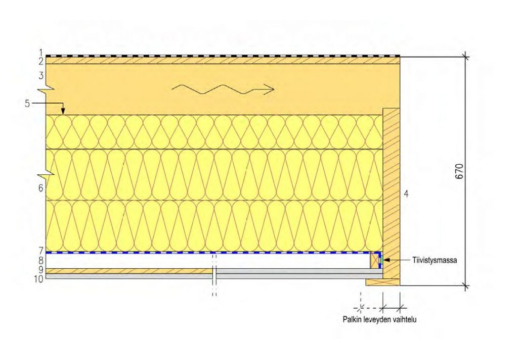
Roof elements may be ventilated or non-ventilated. With ventilated elements, the roof must be of sufficient height between vents and there must be unobstructed ventilation of the roof elements as a whole. Instructions for specifying the distance between vents in a roof constructed in situ can be fond in e.g. RIL 107-2012 table 10. Smaller vent spacing may be used in factory-made waterproof roof elements.With non-ventilated roofs, the waterproof layer must be fixed directly on top of the thermal insulation. Kerto-Ripa elements form a non-ventilated structure according to RakMK C4.
External walls
Wood-framed external wall elements can be either load-bearing or non load-bearing.
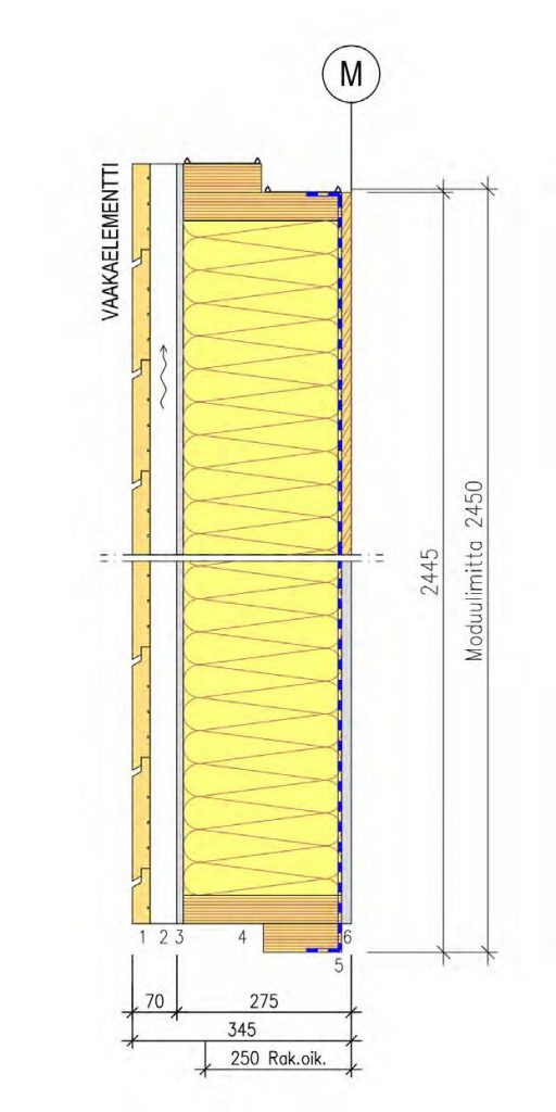
Non load-bearing elements are fixed to a separate frame with screwed joints. Non load-bearing external wall elements are normally fixed horizontally and include the secondary structures between the primary supports. The elements transfer wind loads to the primary structure. The most economic alternative is to use elements with two or three openings. When designing elements, the potential function of the element as a stiffening structure for columns should be taken into account. If the external wall acts to prevent buckling, the frame and joints should be designed in such a way that the wall is able to transfer any support to stiffeners in the primary frame or to some other stiffening structure.
Load-bearing external wall elements should be designed as vertical elements. The wall height may be substantial when the buckling resistance of vertical studs is taken into account. The load-bearing capacity of the element may be increased by using several vertical studs in parallel or by using laminated wood or LVL vertical studs. Wooden boards can be used on the inside of the elements to stiffen the vertical studs and the entire building. The internal cladding is fixed on top of the stiffening boards.